
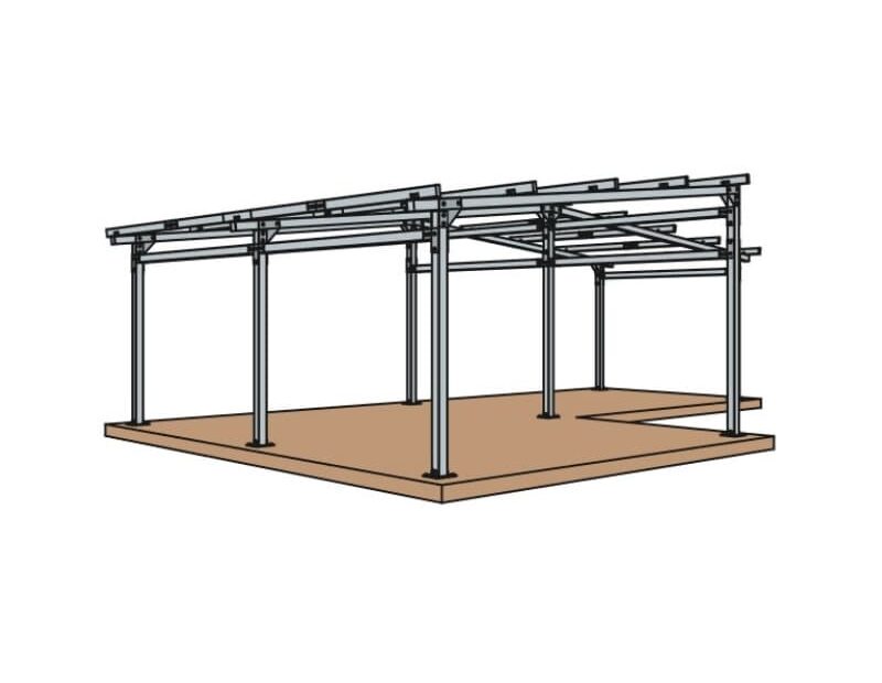
An individual quote requires the dimensions and a clear understanding of what you are measuring. Prepare a simple sketch showing sides, roof, floor, veranda and openings. Then complete the form for a metal structure in your dimensions. KitBolt supplies metal kits for bolted assembly by the customer; panels and decking are supplied by you.
Start with orientation and units
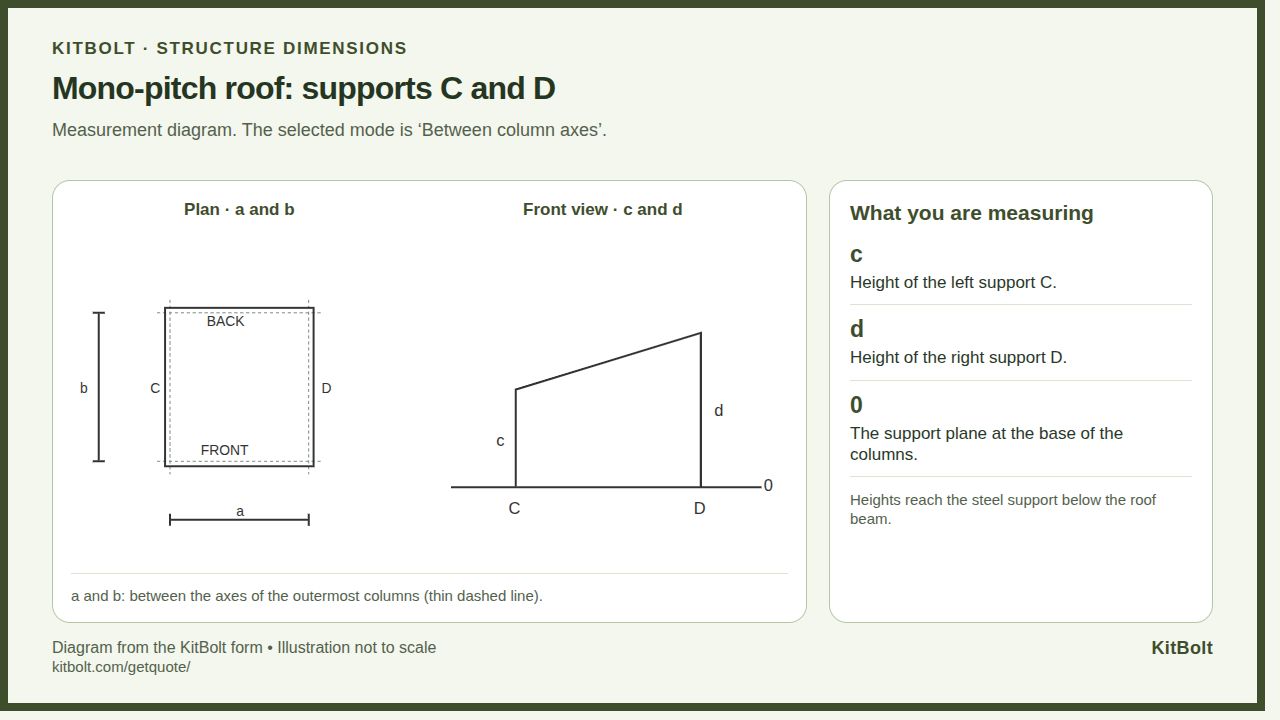
Look at the plan from above: C is the left side, D the right, the front is at the bottom and the back at the top. The origin is the front-left corner. The width a is between sides C and D; the length b is from the front to the back. Use the same labels on your sketch.
Dimensions of the structure, overhangs, veranda and openings are in metres, for example 3,20 m. Panel thickness and effective cover width are in millimetres. Do not enter a value in a field that uses a different unit.
Choose what a and b mean
The question ‘How should we determine the width and length?’ has three options:
- ‘Between column axes’ — specify distances between the centrelines of the outermost columns.
- ‘Exact outside dimensions’ — for wall panels, specify the envelope at their outside faces; on unclad sides, use the column faces. Without wall panels, dimensions are at the outside faces of the outermost columns. State which walls will be clad and the panel thickness.
- ‘Whole effective widths of wall panels’ — enter a positive whole-number panel count in both directions. This mode requires panels on all four walls. Specify the effective cover width and thickness, review the calculated outside envelope and confirm whether it suits you.
Overhangs and the veranda are entered separately from a and b; the outside envelope also excludes flashings. For outside dimensions, enter the chosen envelope without converting it to axes yourself. If the site has a dimensional restriction, describe it in ‘Additional information’.
Heights c and d: from the base to the steel support
| Size | Mono-pitch roof | Gable roof |
|---|---|---|
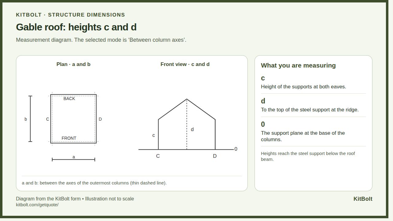
| c | Top of the left support C | Top of the eaves supports |
| d | Top of the right support D | Top of the steel support at the ridge |
Both heights start from the support plane at the base of the columns, marked 0. They end at the support below the roof beam. Clear internal height and the top of the roof covering are different measurements. If you only know the clear height you need, describe it for clarification.
For a gable roof, the ridge position is specified as a percentage between axes C and D, starting from C. 50% means the middle. If you have not chosen the roof yet, use the advice option and leave unknown heights for clarification.
Panels, overhangs, floor and veranda
Use the panels’ technical datasheet. For wall panels, specify the overall thickness; for roof panels, the nominal thickness excluding the raised rib. Effective cover width is the width covered after joining the adjacent panel. Check that the displayed 1000 mm matches your product. A different effective width is clarified when preparing the quote. Add a manufacturer, model or link if available.
Measure each roof overhang horizontally from the axis of the outermost columns. Enter 0 for a side without an overhang. Do not measure along the roof slope.
For an internal metal floor, specify the level from the same base 0 to the top of the steel profiles, excluding decking. Level 0 is allowed. The form provides a frame across the full floor area; describe a partial floor separately. A raised floor does not change the origin for c and d or for openings.
For the veranda, specify the horizontal projection from the column axis to the outside edge of the floor frame. Where complete adjoining sides are selected, the corner is included. For a partial veranda, describe the side, length and position. Add the desired level, decking and intended use; the roof and supports are clarified separately.
Openings and checks before sending
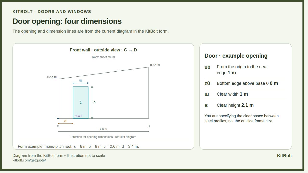
Specify clear dimensions between steel profiles for the door or window, rather than the outside frame size. x0 reaches the near edge of the opening: on C/D, it starts at the front edge; on the front/back wall, at the left edge C. z0 is from base 0 to the bottom edge. Use the labelled origin in the diagram and describe any unclear position.
Review the summary. Use the clarification or advice option where available. If you do not know the required width or length, contact us before sending; do not replace an unknown dimension with 0. Read how a custom-kit request works and how an example price differs from an individual quote. The priced examples show configurations for comparison.